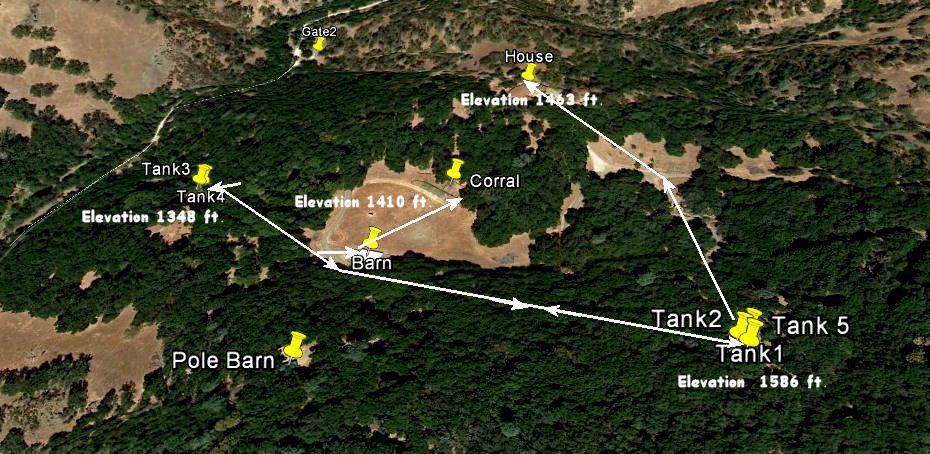
The system is basically comprised of five water tanks, one submersible pump and an array of valves along with a few relays and float switches.
Two of the water tanks are used to collect water from a natural spring and the other three store and distribute water via gravity
to the house, barn and irrigation systems throughout the property.
It must be understood from the onset that this particular system is not without flaws. It has been around for many years and has been added too, modified and repaired
many times. Originally the system had only the composite (fiberglass) tank 2 and most likely only one tank where it now has Tanks 3 & 4. This was no doubt done to accommodate
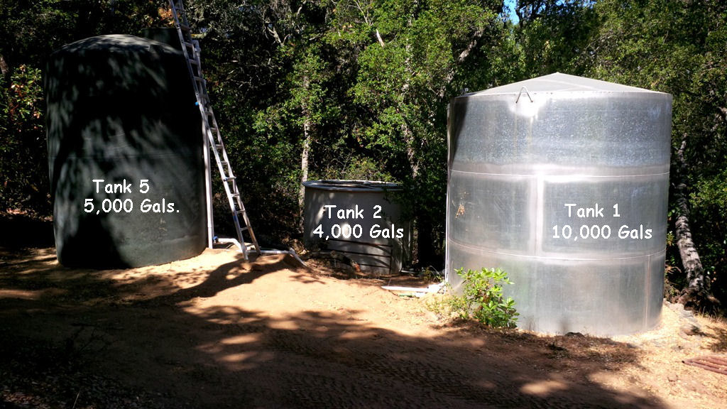
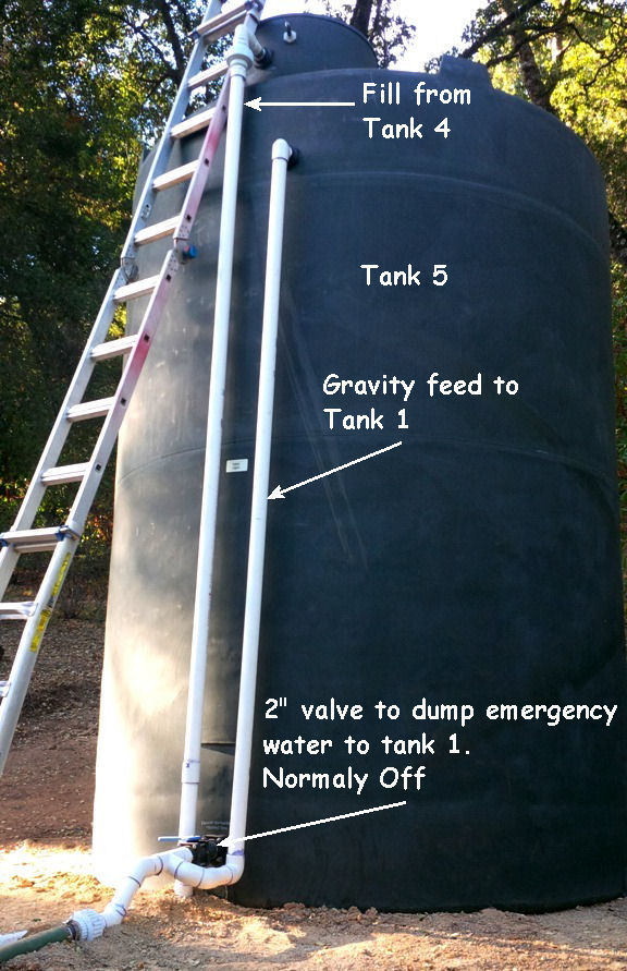
the fire sprinkler system added to the house for insurance purposes. Tank 5 has been added to give the system a 4,000 gallon backup supply in case a broken line, or leak, should drain the system, which has happened. All in all it is still a system that works well with few repairs being required.
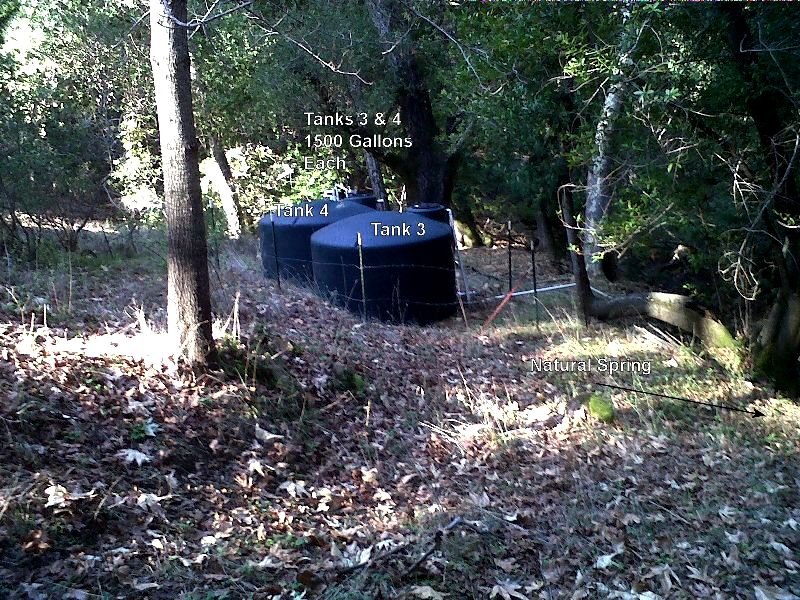
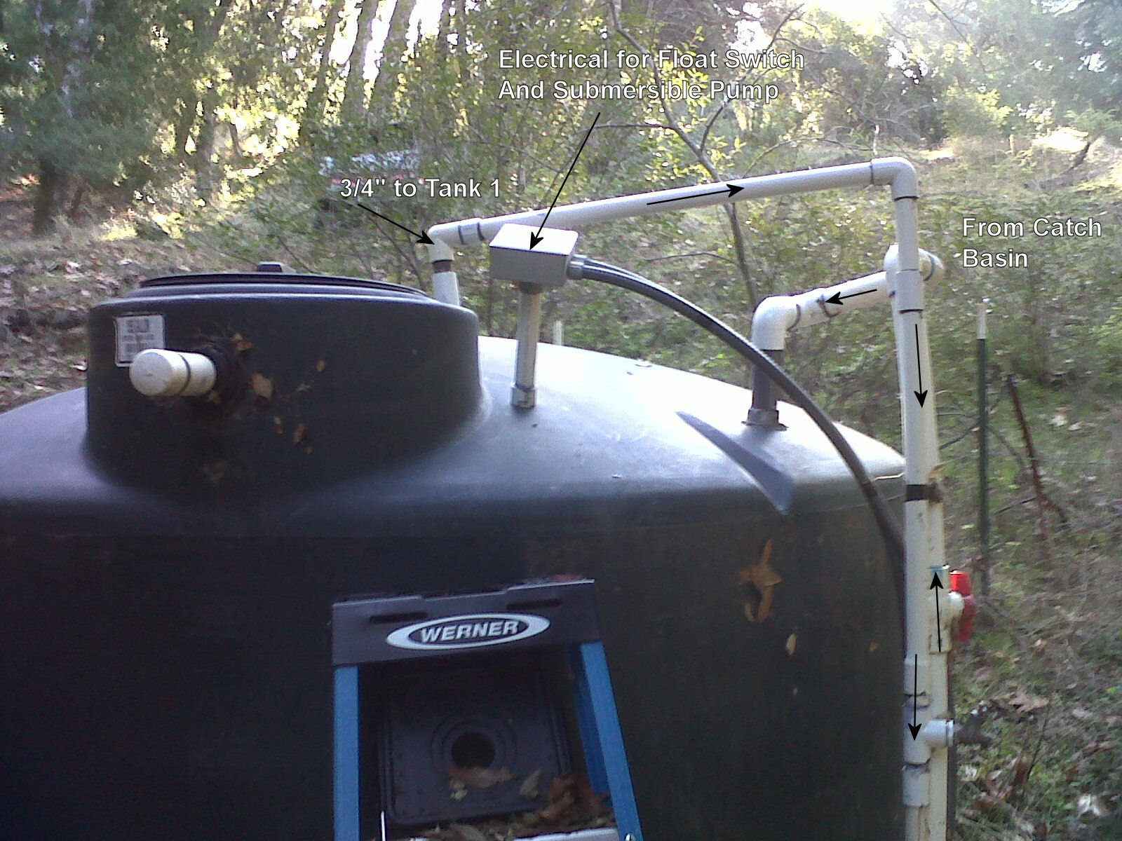
The system starts at the spring which drifts gently down a few feet into a catch basin approximately two feet in diameter installed in the path of a creek. Water from
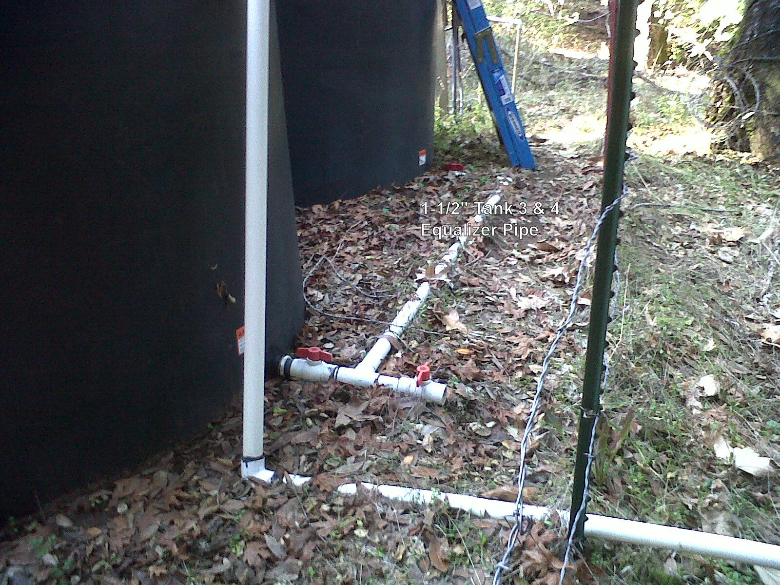
the catch basin gravity feeds gently down through an 1-1/2" PVC pipe into the top of Tank 4. Water from Tank 4 is equalized into Tank 3 via an 1-1/2" PVC equalizer pipe connecting
the two tanks at their bases.
Tank 4 houses near it's base a 1 horspower submersible deep well pump and a tethered float switch approximately centered on the pumps upward 1" PVC discharge pipe. When Tank 4
fills to approximately 3/4 capacity the float switch changes to an on state. On the other hand if Tank 4 water level drops below 1/4 capacity the float switch changes it's
state to off, in an effort to not cavatate and damage the pump.
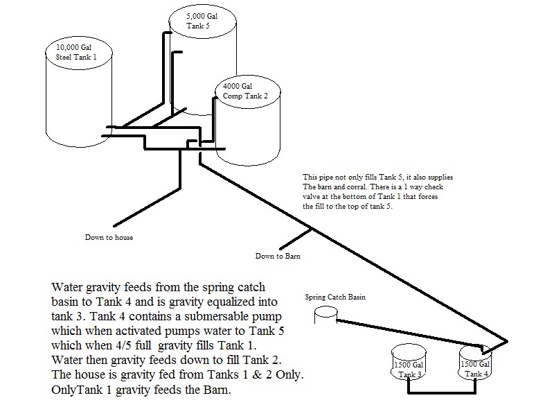
When activated the submersible pump, housed in Tank 4, forces the water contained in tanks 3 & 4 up approximately 250 feet and 1/4 mile distance to fill Tank 5.
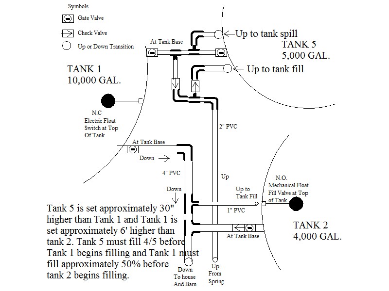
The water received from Tanks 3 & 4 is dumped into the top of Tank 5 which when approximately 4/5 full begins to gravity fill Tank 1. Tank 1 houses another tethered float
switch at it's top which deactivates the submersible pump when Tank 1 reaches maximum capacity.
 Tank 2 houses a mechanical float at it's top which stops it's filling process when maximum capacity
is achieved. The water contained in Tanks 1 & 2 is then gravity fed down to the house and irrigation systems while only Tank 1 gravity feeds the barn.
Tank 2 houses a mechanical float at it's top which stops it's filling process when maximum capacity
is achieved. The water contained in Tanks 1 & 2 is then gravity fed down to the house and irrigation systems while only Tank 1 gravity feeds the barn.
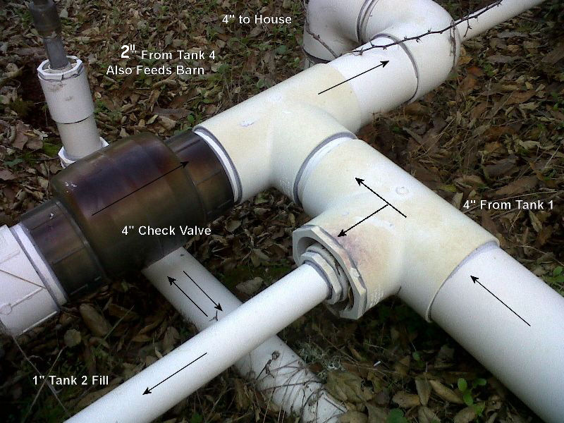
Clarification is needed at this point on one of the system flaws. The barn is being gravity fed through the same pipe which feeds water from Tank 4 to Tank 1. This no doubt happened
because originally the barn required little water so the line from Tank 4 feeding up to Tank 1 was tapped and a 3/4" PVC pipe routed to the Barn. This would furnish a fair water supply
to the barn when the pump was running, which is not always the case as you will see later.
Update :
The barn has been upgraded to a 2" supply pipe.
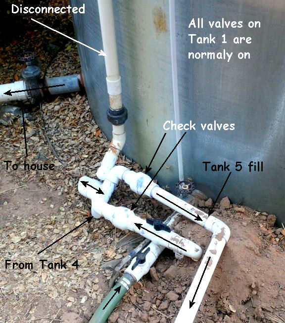
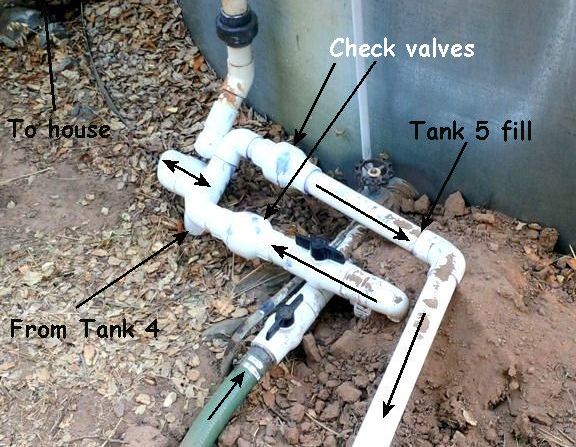
A fire stand pipe was added at the barn I'm sure for the same reason Tank 1 was added, insurance requirements. To increase water availability at the barn without
digging a very long trench and installing another water supply pipe, water from the base of Tank 1 was induced into the fill pipe for Tank 5 through a one way check valve, See below.
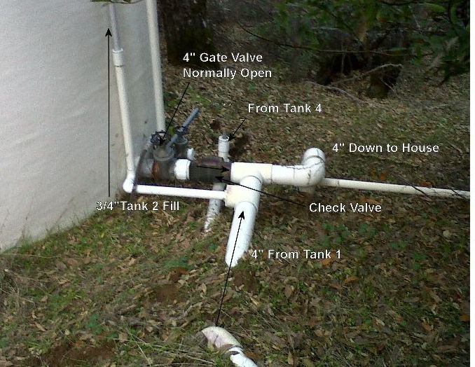
This is a plan view of the plumbing and valves at Tank 1 which basically make the system function.
When the going gets tough, the tough get going